A small arrow on a valve body can prevent a serious installation mistake. It shows the manufacturer’s intended flow direction, but it is not decoration. Understanding how to read the flow direction arrow on a valve body helps technicians protect seats, discs, seals, pumps, and downstream equipment.
Philip L. Skousen, author of Valve Handbook, states, “The direction of flow through a valve is an important consideration in valve selection and installation.” This principle remains practical in the field. Stand beside the valve. Clean the casting. Trace the arrow from its tail to its pointed tip. That is the expected flow path. Never rely only on the handle position, pipe layout, or an old installation drawing.
Details matter. A check valve may fail immediately when installed backward. A globe valve can perform poorly against its intended flow direction. A control valve may produce unstable operation, noise, or excessive wear. Before tightening bolts, compare the arrow with the process-flow diagram and the equipment manual. Then confirm the actual pipeline flow, because drawings can be outdated.
It is easy to overtrust one mark. That is the weak point. Some valves have directional arrows for preferred operation, while others require strict orientation. The body arrow may also differ from the actuator’s opening direction. Good practice means checking the valve type, pressure rating, seat design, and manufacturer instructions together. A flashlight, a clean surface, and one careful pause can prevent hours of rework.
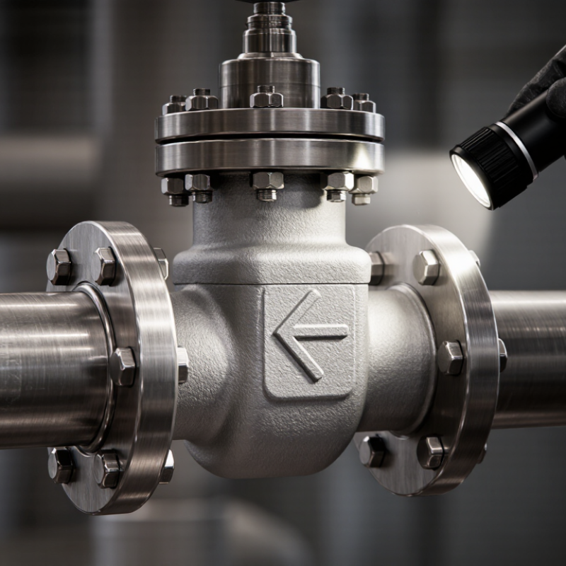
When you inspect a valve, look for the flow direction arrow on its body. The arrow usually appears near the ports, cast into metal or painted on the surface. Its basic meaning is simple: fluid should enter at the tail and leave at the arrowhead. That sounds obvious. Yet dirt, insulation, and worn paint can hide it during maintenance.
The arrow shows the valve’s intended flow path, not its pressure rating or open position. On a globe valve, the direction can support better control and reduce seat damage. A check valve normally follows the arrow automatically, allowing flow in one direction only. Some valves work in either direction and may have no arrow. Never assume every valve behaves the same way.
In field inspections, I compare the body arrow with the pipe labels and the process drawing. The stem position can help, but it is not a reliable substitute. I have occasionally trusted a faded arrow and missed an installation mistake. That is a useful reminder. Clean the body carefully, confirm the inlet and outlet, and check the valve’s technical documentation before changing the piping. If the arrow conflicts with the drawing, stop and investigate the actual service conditions.
The arrow may be cast, stamped, or painted on the valve body. It shows the intended fluid path, but its meaning depends on the valve type. On a check valve, the arrow is critical. It must point from inlet to outlet, allowing forward flow and preventing reverse flow. A globe valve usually follows the arrow to improve disc stability and reduce seat damage. Gate valves often work in either direction, although the piping design may specify one direction.
Ball and butterfly valves can be bidirectional when their bodies show no directional marking. However, some designs include a preferred flow arrow because pressure affects sealing performance. A technician should never guess from the handle position. Compare the arrow with the valve tag, piping drawing, and manufacturer’s installation instructions. API 6D emphasizes documented valve orientation and functional testing for pipeline valves. The U.S. Department of Energy also reports that pumping systems can consume roughly 20–30% of industrial electricity, so incorrect flow direction may increase resistance, maintenance, and energy waste. That figure varies by facility, but it deserves attention.
Tips: Clean the body before reading the arrow. Trace the pipe from source to equipment. For a check valve, verify the internal hinge or disc direction. If the arrow is unclear, stop and inspect the manual. A rushed visual check can be wrong. Even experienced workers occasionally trust the handle instead of the body marking.
How to Read the Flow Direction Arrow on a Valve Body?
Reading the Arrow Against the Media Flow Path
A valve body arrow shows the intended direction of media movement. It does not show the direction of the handle. Stand beside the pipe and trace the path from the source toward the equipment. Then compare that path with the cast or stamped arrow on the valve body.
Look closely near the inlet and outlet. The arrow may be shallow, covered by paint, or partly hidden under insulation. Use a flashlight and clean the surface gently. I have seen installers follow the handle position instead of the body marking. That mistake can reverse the pressure relationship inside the valve.
For steam, water, gas, or chemical service, confirm the actual flow path from the piping drawing and site labels. A pump discharge is usually downstream, but temporary hoses can change the expected route. Pressure-reducing and control valves often require a specific direction. Some isolation valves can work both ways, yet their arrows may identify the preferred installation direction. Check the technical documentation before tightening the final connection.
When the arrow points against media flow, stop and investigate. Do not rotate the valve by guessing. Verify upstream pressure, downstream equipment, and any check-valve effect. A reversed valve may leak, respond poorly, or suffer internal damage. My own inspections improved after marking the flow path on the pipe first; relying on memory was not reliable enough.
| Step | Inspection Point | Arrow Interpretation | What to Verify | Correct Condition | Risk if Installed Incorrectly | Recommended Action |
|---|---|---|---|---|---|---|
| 1 | Locate the molded, cast, or stamped arrow | → Follow the arrow tip | Confirm that the marking is on the valve body rather than on a removable handle, actuator, or nearby pipe. | Arrow clearly visible | Using the wrong marking can reverse the intended installation direction. | Clean the body surface and identify the arrow before connecting the valve. |
| 2 | Compare the arrow with the media flow path | Pipe flow must match → | Trace the process line from the upstream source toward the downstream equipment, not merely from left to right. | Media flows in the arrow direction | Reverse flow may reduce shutoff performance, increase noise, or create abnormal pressure loading. | Rotate or reinstall the valve so the body arrow points downstream. |
| 3 | Identify upstream and downstream sides | Upstream → Downstream | Use the piping layout, pump discharge, tank outlet, or process-flow drawing to determine the actual direction. | Inlet and outlet are confirmed | Assuming direction from physical location can cause an incorrect installation when piping changes elevation or orientation. | Confirm the flow path against the approved piping and instrumentation documentation. |
| 4 | Check the valve type | Direction may be mandatory | Globe valves, many check valves, pressure-reducing valves, control valves, and some lined or specialty valves commonly use directional arrows. | Valve instructions match the body marking | A valve designed for a preferred direction may not perform correctly when reversed. | Use the valve nameplate, body marking, and applicable installation instructions together. |
| 5 | Check a check valve specifically | → Normally indicates permitted forward flow | Verify that the arrow points from the intended low-pressure side toward the protected downstream side. | Forward flow is permitted; reverse flow is blocked | A reversed check valve can block normal flow or fail to prevent backflow. | Install the check valve with the arrow pointing toward the desired flow destination. |
| 6 | Check pressure and temperature limits | Direction alone is not enough | Compare the valve rating with the system pressure, temperature, fluid state, and connection specification. | All service conditions are within rating | A correctly oriented valve can still fail if pressure, temperature, or material compatibility limits are exceeded. | Verify the rating information before commissioning the line. |
| 7 | Inspect the installation position | → Must remain aligned after positioning | Check whether the valve is installed in the permitted orientation, especially for check, control, and actuated valves. | Body arrow and installation orientation agree | Some valves may malfunction because of gravity, incorrect actuator position, or unsuitable mounting orientation. | Follow the valve-specific orientation requirements and support the piping independently. |
| 8 | Confirm flange or threaded connection alignment | Flow direction remains unchanged | Ensure that the valve is not rotated or forced into alignment during bolting or threaded assembly. | No pipe strain or forced alignment | Mechanical stress can distort the body, damage seats, or create leakage even when the arrow direction is correct. | Align the pipework first and tighten connections using the specified installation practice. |
| 9 | Perform a pre-start inspection | Arrow points downstream | Check the arrow, connection tightness, actuator position, drains, vents, and temporary protective materials before introducing media. | Installation is ready for controlled startup | Unexpected flow, leakage, or pressure surges can occur during startup. | Use a documented checklist and remove tools, caps, and shipping restraints from the line. |
| 10 | Respond to a conflicting arrow and process drawing | Do not assume either is correct | Resolve any disagreement between the valve arrow, piping layout, and process documentation before operation. | Conflict resolved and documented | Operating a valve with an unresolved directional conflict can cause equipment damage or unsafe process conditions. | Stop the installation review and obtain confirmation from the responsible engineering or maintenance authority. |
| 11 | Verify flow after startup | Measured flow agrees with → | Use approved indicators such as flow meters, pressure readings, temperature behavior, or system response. | Operating behavior confirms the intended path | Incorrect flow may remain unnoticed if the valve is not tested under operating conditions. | Introduce media gradually and monitor for leakage, vibration, unusual noise, and abnormal pressure drop. |
| 12 | Record the final inspection | Direction is traceable | Document the valve location, flow direction, inspection date, test result, and any corrective work. | Maintenance record completed | Future maintenance personnel may repeat an incorrect installation if the verified direction is not recorded. | Mark the flow path on relevant drawings or inspection records where permitted by site procedures. |
The arrow cast on a valve body shows the intended flow direction, but it is not the only installation check. During field inspections, I compare the arrow with the pipe flow mark, process drawing, and valve documentation. I once assumed a similar-looking valve worked in both directions. The specification proved otherwise. That mistake was caught before operation, but it showed why visual checks alone are unreliable.
Confirm the valve orientation before tightening each connection. For a check valve, the arrow must follow the normal process flow. A control valve may also require a defined inlet and outlet to manage pressure correctly. Verify the actuator position indicator, stem movement, and nearby open or closed labels. The valve should match the required operating position, not merely appear aligned. Keep it fully open during flushing only when the procedure allows it. Some valves can be damaged by forced flow or unsuitable throttling.
Check the line is depressurized before correcting orientation. Use pressure gauges upstream and downstream when available. Their readings can reveal an unexpected restriction or a valve that is not fully open. The handwheel may turn, yet the internal disc can remain partly seated. I have learned to confirm movement at the indicator, not by touch alone. Record the final position and inspect for leaks after gradual pressurization. Small details matter here.
The arrow molded or stamped on a valve body indicates the intended direction of fluid movement. During installation, the arrow should point from the upstream side toward the downstream side. The chart shows the mechanical position reference for a typical quarter-turn valve, where the actuator rotates through 90 degrees from closed to open.
Reading the valve: Confirm that the body arrow follows the planned flow direction, then check the actuator position. A 0° position represents closed, while a 90° position represents fully open. Mechanical position does not directly equal flow rate because actual flow also depends on valve design, pressure difference, and system resistance.
How to Read the Flow Direction Arrow on a Valve Body?
Avoiding Common Errors When Interpreting Flow Direction Arrows
A flow direction arrow is usually cast, stamped, or engraved on the valve body. It shows the intended movement of fluid through the valve. Do not use the handle position as your guide. A handle can point sideways while the internal passage follows another direction. Before installation, trace the pipe route and compare it with the arrow. The fluid should enter at the marked inlet and leave at the marked outlet.
Small details matter. Dirt, paint, insulation, or corrosion can hide part of the arrow. Clean the surface carefully, but never remove important markings. Check the valve drawing, maintenance record, and piping layout when the arrow is unclear. A check valve, pressure-control valve, or globe valve may not operate safely with reversed flow. Some valves might still pass fluid, which creates a dangerous false impression.
I have seen experienced workers make this mistake during rushed maintenance. The valve looked symmetrical, so the arrow was ignored. That assumption caused poor shutoff and repeated inspection work. Stop and verify. If no reliable arrow or document exists, do not guess. Isolate the line, release stored pressure, and ask a qualified engineer to confirm the direction. My own early inspections were not perfect either; I once checked the arrow but missed a second valve installed nearby. That error changed the actual flow path.
It shows the intended direction of fluid movement. It does not show handle movement. The arrow may be cast, stamped, or painted.
Trace the pipe from the source toward the equipment. Then compare that path with the body arrow. Marking the pipe first helps. Memory alone can mislead.
A check valve should point from inlet to outlet. This allows forward flow and limits reverse flow. A reversed installation may stop the system from working correctly. Small mistake, large effect.
Gate valves often operate in either direction. However, the piping design may specify a preferred direction. Read the drawing before making the final connection.
Some can work bidirectionally when no directional marking exists. Other designs include an arrow because pressure affects sealing. Never decide from the handle position alone.
Check, pressure-reducing, and control valves commonly require careful orientation. Globe valves usually follow the arrow for better disc stability. This can also reduce seat damage.
Clean the valve body gently and use a flashlight. Paint, insulation, or shallow markings may hide the arrow. If it remains unclear, stop and inspect the manual. Do not guess.
It may leak, respond poorly, or suffer internal damage. Incorrect direction can also increase resistance and maintenance needs. Verify upstream pressure, downstream equipment, and temporary hose routing. A visual check is not always enough.
Understanding how to read the flow direction arrow on a valve body is essential for safe and effective installation. The arrow indicates the intended direction of media movement through the valve and is usually cast, stamped, or printed directly on the body. To interpret it correctly, first locate the arrow and compare its direction with the valve type, such as a check, globe, ball, or control valve, because some valves may have specific operating requirements. The arrow should align with the actual flow path in the piping system.
Before installation, verify the valve’s orientation, inlet and outlet connections, and the position of the handle or actuator. Do not rely only on appearance, as the correct direction may vary depending on the valve design. Common mistakes include reversing the valve, confusing the arrow with a pressure or identification mark, and ignoring the system’s normal flow direction. Careful inspection helps prevent poor performance, leakage, and unnecessary maintenance.

Maria Valve